


custom aluminum CNC machining controls the fin shape, base flatness, and thermal contact that determine how well an aluminum heat sink removes heat. A heat sink can have high thermal conductivity and still perform poorly if the base does not touch the heat source evenly. Fin spacing, airflow resistance, surface roughness, and mounting pressure also affect the final result.
Introduction: Why Heat Sink Machining Accuracy Matters
Aluminum heat sinks are widely used in LED lighting, power electronics, electric vehicles, telecommunications, and industrial control systems. The most common materials include 6061-T6 aluminum and 6063 aluminum because they offer a good balance of strength, weight, corrosion resistance, and thermal conductivity.
For a custom aluminum heat sink, the design must match the heat load, airflow, installation space, and production method. A small change in fin thickness or base flatness can change the thermal resistance by a measurable amount.
Summary Answer: How Should an Aluminum Heat Sink Be CNC Machined?
The best CNC machined aluminum heat sink uses a flat and stable base, correctly sized fins, controlled surface roughness, and a low-resistance thermal interface. For many applications, 6061-T6 or 6063 aluminum is suitable. A practical design may use a base thickness of 3 to 8 mm, fin thickness of 0.8 to 2.0 mm, fin spacing of 1.5 to 5.0 mm, and base flatness of 0.03 to 0.10 mm, depending on size and heat load. The final design should be verified with dimensional inspection and thermal testing under the actual airflow and mounting conditions.
1. Select the Right Aluminum Grade for CNC Heat Sinks
Aluminum grade affects thermal performance, machinability, strength, anodizing, and cost. The most suitable alloy depends on the heat sink geometry and installation environment.
6061-T6 Aluminum
6061-T6 is a common choice for custom aluminum CNC machining. It has good strength and stable machining behavior. Its typical thermal conductivity is about 167 W/m-K at room temperature. It is suitable for electronic housings, power supply heat sinks, motor controllers, and structural cooling parts.
6063 Aluminum
6063 aluminum is often selected when thermal conductivity and surface appearance are more important than high structural strength. Its thermal conductivity can be about 200 W/m-K, depending on the temper and material source. It is suitable for LED heat sinks and designs with long, thin fins.
Aluminum Material Comparison
| Material | Typical Thermal Conductivity | Machinability | Common Heat Sink Use |
|---|---|---|---|
| 6061-T6 | About 167 W/m-K | Good | Power electronics, motor controllers, housings |
| 6063-T5 or 6063-T6 | About 200 W/m-K | Good | LED lighting, thin fin profiles, visible products |
| Aluminum 1050 | About 220 W/m-K | Moderate | High conductivity parts with low structural loads |
Actual values depend on the material temper, supplier certificate, temperature, and test method. A production drawing should state the required alloy and temper. Jixing can use material certificates and incoming inspection records to confirm the material before machining begins.
2. Design Fin Geometry for Heat Transfer and Airflow
Fin geometry controls the surface area available for heat transfer. It also controls air resistance, tool access, machining time, and the risk of fin vibration.
- Define the heat load in watts.
- Set the allowed component temperature.
- Identify natural convection or forced airflow.
- Choose fin height, thickness, spacing, and direction.
- Check tool access and minimum corner radius.
- Review the design for machining, cleaning, and inspection.
Fin Thickness
For a CNC machined aluminum heat sink, fin thickness is often between 0.8 and 2.0 mm. A 1.0 mm fin can reduce weight and increase surface area, but it requires stable workholding and suitable cutting tools. A 1.5 to 2.0 mm fin provides greater strength and is easier to machine in many designs.
Fin Spacing
Fin spacing must match the airflow condition. Narrow spacing increases surface area but can restrict air movement. Wider spacing reduces pressure loss but may reduce the total cooling area.
| Cooling Condition | Typical Fin Spacing | Design Focus |
|---|---|---|
| Natural convection | 3.0 to 8.0 mm | Allow warm air to rise through the fins |
| Low-speed fan cooling | 2.0 to 5.0 mm | Balance surface area and airflow resistance |
| High-speed forced air | 1.5 to 3.5 mm | Increase area while checking fan pressure |
These values are starting points, not universal rules. Thermal simulation or physical testing should confirm the final fin pitch.
Fin Height and Aspect Ratio
Fin height is commonly between 10 and 50 mm for CNC machined aluminum heat sinks. Very tall and thin fins may bend during machining or transport. A useful design check is the fin height-to-thickness ratio. Ratios above 20 to 1 require careful tool selection, cutting conditions, and workholding.
Fin Direction
For natural convection, fins should normally support vertical airflow. For forced air, fins should align with the fan flow direction. Cross-flow designs can increase turbulence, but they may also increase pressure loss.
3. Control Base Flatness for Better Thermal Contact
The heat sink base transfers heat from the device into the aluminum body. If the base is warped, the thermal interface material becomes uneven. This creates air gaps and increases thermal resistance.
Recommended Flatness Ranges
| Heat Sink Base Size | Typical Flatness Target | Typical Application |
|---|---|---|
| Up to 100 mm | 0.03 to 0.05 mm | Small LED and electronic modules |
| 100 to 250 mm | 0.05 to 0.10 mm | Power supplies and control systems |
| Over 250 mm | 0.10 to 0.20 mm | Large enclosures and industrial cooling plates |
The correct tolerance depends on the size, thickness, mounting method, and thermal interface material. A drawing may specify flatness according to ASME Y14.5 or a general tolerance standard such as ISO 2768. Flatness is measured over the stated datum or reference surface. It is not the same as parallelism.
How CNC Machining Can Cause Warping
Aluminum releases internal stress during material removal. Heat from cutting can also change the shape of a thin base. Removing too much material from one side can produce a concave or convex surface.
Jixing can reduce this risk by using rough machining, controlled stress relief when required, rest time, and a separate finishing operation. A common process leaves 0.2 to 0.5 mm of stock for the final base pass. The final pass should use stable clamping and consistent cutting pressure.
4. Reduce Thermal Contact Resistance
Thermal contact resistance occurs at the joint between the heat source, thermal interface material, and heat sink. It depends on surface flatness, roughness, contact pressure, interface thickness, and material selection.
Surface Roughness
A machined base surface with an Ra value of 1.6 to 3.2 micrometers is suitable for many thermal interface applications. Some high-performance interfaces may require Ra below 1.6 micrometers. The required value should match the thermal pad, grease, phase-change material, or adhesive used in the assembly.
Mounting Pressure
Mounting screws must apply enough pressure to close surface gaps without damaging the electronic component. Uneven screw torque can tilt the device and create a high-resistance area.
For example, a four-screw mounting pattern should normally use a cross-tightening sequence. The assembly specification should define screw size, torque, washer type, and thermal interface thickness. A typical thermal pad may be 0.5 to 2.0 mm thick, while thermal grease is often applied at a much thinner layer.
Thermal Interface Material Comparison
| Interface Material | Typical Thickness | Advantages | Limitations |
|---|---|---|---|
| Thermal grease | Less than 0.20 mm when compressed | Low interface resistance and good gap filling | Requires controlled application |
| Thermal pad | 0.50 to 2.00 mm | Clean installation and easy assembly | Higher resistance at greater thickness |
| Phase-change material | About 0.05 to 0.20 mm | Thin bond line after heating and pressure | Needs correct assembly temperature |
| Thermal adhesive | 0.10 to 0.50 mm | Provides mechanical bonding | Can make service removal difficult |
5. Use a Controlled CNC Machining Process
A repeatable process helps control fin dimensions, base flatness, hole position, and surface finish. The following flow is suitable for many custom aluminum heat sink projects.
Step-by-Step CNC Heat Sink Manufacturing Flow
- Review the 3D model, 2D drawing, heat load, airflow, and installation points.
- Confirm aluminum alloy, temper, stock size, and material certificate.
- Perform a design for manufacturability review.
- Rough machine the outer profile, mounting features, and fin channels.
- Control cutting heat with suitable spindle speed, feed rate, coolant, and chip removal.
- Inspect the rough part for distortion and remaining stock.
- Finish machine the base, fins, holes, and datum surfaces.
- Deburr the part without rounding critical thermal edges.
- Clean the part with a controlled process to remove chips and cutting fluid.
- Complete dimensional, flatness, surface roughness, and visual inspection.
- Apply anodizing or another surface treatment if required.
- Perform final inspection and thermal testing when specified.
Equipment Selection
A three-axis machining center can produce many standard heat sinks. A four-axis or five-axis machine may be useful for angled fins, complex mounting features, or reduced setup error. A high-speed spindle with a speed range of about 12,000 to 24,000 revolutions per minute can support small aluminum tools, but the correct speed depends on tool diameter, flute count, depth of cut, and machine rigidity.
Typical tools include carbide end mills, slot drills, ball nose cutters, and small-diameter tools for narrow channels. Tool runout should be checked because excessive runout can create uneven fin thickness and poor surface finish.
6. Apply Practical Quality Inspection Standards
Quality inspection should focus on the features that affect heat transfer and assembly. A general visual inspection is not enough for a precision aluminum heat sink.
Recommended Inspection Plan
| Feature | Inspection Method | Example Control Target |
|---|---|---|
| Overall dimensions | Caliper, micrometer, or CMM | According to drawing tolerance |
| Base flatness | Granite surface plate and dial indicator or CMM | 0.03 to 0.10 mm when specified |
| Fin thickness | Optical measurement or calibrated gauge | Plus or minus 0.05 to 0.10 mm |
| Fin spacing | Vision system, gauge, or CMM | Plus or minus 0.05 to 0.15 mm |
| Mounting holes | CMM, pin gauge, or functional fixture | Position tolerance according to drawing |
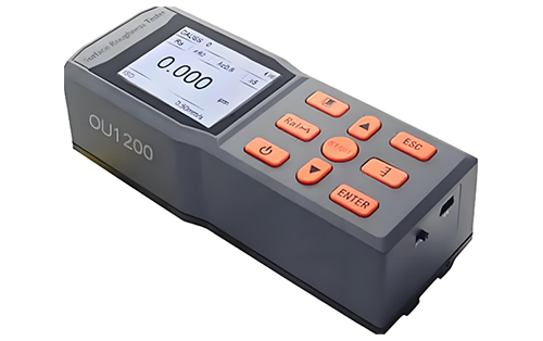
| Surface roughness | Contact profilometer | Ra 1.6 to 3.2 micrometers when specified |
| Material identity | Certificate review and alloy verification | 6061-T6, 6063, or specified grade |
For critical production, a supplier may inspect 100 percent of the base flatness and mounting hole pattern. A sampling plan can be used for non-critical cosmetic features. Inspection equipment should have a calibration record, and the measurement uncertainty should be suitable for the tolerance being checked.
Common Testing Standards
ASME Y14.5 can be used for geometric dimensioning and tolerancing. ISO 2768 may be used for general dimensional tolerances. ISO 9001 provides a quality management framework. Surface treatment tests may include coating thickness, color, adhesion, and corrosion checks. Salt spray testing according to ASTM B117 may be used when corrosion resistance must be evaluated, although the test duration should be agreed before production.
7. Choose Surface Treatments Carefully
Surface treatment can improve corrosion resistance, appearance, electrical insulation, and wear resistance. It can also affect contact dimensions and thermal behavior.
Anodizing
Clear or black anodizing is common for aluminum heat sinks. A typical anodized layer may be 5 to 25 micrometers thick. Type II anodizing is often selected for general protection. Type III hard anodizing can provide a thicker and harder layer, but it may change dimensions more significantly.
Anodizing can improve emissivity. This may help radiation cooling in natural convection applications. However, the base area under a thermal interface should remain free of coating when the design requires direct metal contact. The drawing should clearly identify masked areas.
Deburring and Cleaning
Small chips left between fins can reduce airflow and become loose inside electronic equipment. Burrs around mounting holes can prevent correct seating. A complete process should include deburring, washing, drying, and inspection under suitable lighting.
8. Avoid Common Custom Aluminum Heat Sink Problems
Thin Fins That Bend
Fins below 1.0 mm may bend during machining or handling. Increase the thickness, reduce the cutting load, or add temporary support when the design allows it.
Base Warpage
Large thin bases are more likely to warp. Use balanced material removal and a final light finishing pass. Check flatness after the part reaches room temperature.
Wrong Fin Pitch
A fin pitch selected only for maximum surface area may block airflow. Review the fan curve or natural convection path before releasing the drawing.
Uncontrolled Thermal Interface Thickness
A thick thermal pad can increase temperature even when the aluminum heat sink is well machined. Define the interface material, compression range, and mounting torque as part of the complete assembly specification.
Unclear Datum Structure
Without clear datums, the supplier may measure the base, holes, and fins from different reference points. Use the thermal base as a primary datum when its position controls assembly performance.
9. A Practical Example of Design Targets
Consider a 150 mm by 100 mm aluminum heat sink used with a 120 W power module and forced air. A starting design could use 6061-T6 aluminum, a 5 mm base, 25 mm fin height, 1.2 mm fin thickness, and 3.0 mm fin spacing.
| Design Feature | Example Target | Reason |
|---|---|---|
| Base material | 6061-T6 aluminum | Good strength and thermal performance |
| Base thickness | 5 mm | Supports heat spreading and reduces distortion |
| Fin height | 25 mm | Adds cooling area without an excessive aspect ratio |
| Fin thickness | 1.2 mm | Balances area, strength, and machining stability |
| Fin spacing | 3.0 mm | Allows moderate forced airflow |
| Base flatness | 0.05 mm | Improves contact with the thermal interface |
| Base surface roughness | Ra 1.6 to 3.2 micrometers | Supports a thin and even interface layer |
This example is not a final thermal solution. The actual result must be checked using the power module, interface material, fan speed, air temperature, and mounting method used in the product.
10. How Jixing Can Support a Custom Aluminum CNC Project
Jixing can support the project from drawing review through production inspection. A clear workflow should include design review, material confirmation, CNC process planning, sample production, dimensional inspection, surface treatment, and packaging.
For a repeat production order, the quality plan can define first article inspection, 100 percent inspection of critical thermal surfaces, sampling inspection of general dimensions, and inspection reports for each batch. A supplier should also be able to provide material certificates, measurement records, surface treatment records, and corrective action reports when needed.
Before requesting a quotation, prepare the 3D model, 2D drawing, aluminum grade, heat load, target thermal resistance, airflow data, interface material, surface treatment, quantity, and inspection requirements. These details reduce design changes and improve quotation accuracy.
Conclusion
CNC machining aluminum heat sinks requires more than cutting fins from a block of metal. Fin thickness, fin spacing, airflow direction, base flatness, surface roughness, mounting pressure, and thermal interface thickness must work together. A stable material such as 6061-T6 or 6063 aluminum can provide reliable performance when the geometry and manufacturing process are properly controlled.
For reliable custom aluminum CNC machining, define the heat load first, select the correct fin geometry, control the base to the required flatness, and verify the part with calibrated inspection equipment. Working with Jixing or another qualified supplier can help turn the thermal design into a repeatable and testable aluminum heat sink.


