


When we perform Deep Pocket CNC Milling in Aluminum: How to Maintain Accuracy and Surface Finish, we use a controlled process rather than relying on machine settings alone. At Jixing, we can help you reduce chatter, prevent tool deflection, control burrs, and achieve repeatable dimensional accuracy—often to ±0.01 mm on suitable features—by following six practical steps: stabilize the workpiece, select the correct cutter, control chip evacuation, balance cutting parameters, measure critical features, and protect the finished surface.
Why Deep Pocket CNC Milling in Aluminum Is Difficult
Aluminum is highly machinable, but deep cavities create several technical problems that do not appear in shallow pocket milling. As the pocket depth-to-width ratio increases, the cutting tool becomes more flexible, chip evacuation becomes more difficult, and the workpiece may lose rigidity.
These conditions can cause:
- Tool deflection and tapered pocket walls
- Chatter marks on the floor or sidewalls
- Recutting of chips and built-up edge
- Dimensional variation from thermal growth
- Poor flatness at the pocket bottom
- Burr formation around openings and internal corners
- Visible differences in anodizing or other finishing operations
For manufacturers purchasing custom aluminum CNC machining, these problems can lead to assembly interference, leakage, weak wall sections, rejected parts, and additional inspection costs.
The goal of Deep Pocket CNC Milling in Aluminum: How to Maintain Accuracy and Surface Finish is therefore not simply to remove material quickly. The process must maintain rigidity, manage heat, evacuate chips, and preserve the designed geometry from roughing through final inspection.
Jixing’s Process for Deep Pocket CNC Milling in Aluminum
1. Review the CAD Model and Manufacturing Requirements
Before programming, we review the 3D model, 2D drawing, material specification, tolerances, surface-finish requirements, and inspection datums.
Important details include:
- Aluminum grade, such as 6061-T6, 6082-T6, 7075-T6, or 2024-T3
- Pocket depth, width, corner radius, and wall thickness
- General tolerances according to ISO 2768, where applicable
- Geometric tolerances defined by ASME Y14.5
- Flatness, perpendicularity, position, and parallelism requirements
- Surface roughness requirements, such as Ra 0.8 μm, Ra 1.6 μm, or Ra 3.2 μm
- Requirements for anodizing, conversion coating, passivation, or paint
We also identify whether the pocket will be used for a bearing, seal, insert, electronic component, or mating assembly. A pocket for a gasket or precision insert requires a different inspection plan from a nonfunctional weight-reduction cavity.
At Jixing, we recommend adding realistic internal corner radii. A small radius may require a small-diameter tool, which increases cutting time and tool deflection. Increasing the radius where the design allows it can improve both cycle time and surface finish.
2. Select a Rigid Workholding Method
A deep pocket cannot be machined accurately if the workpiece moves or vibrates during cutting. We first determine the best datum structure and clamping method.
Common workholding solutions include:
- Precision vise with soft jaws
- Custom contoured jaws
- Fixture plate with locating pins
- Vacuum fixture for thin plate components
- Modular zero-point clamping
- Multiple locating points for large structural parts
The clamping force must be sufficient to prevent movement without distorting thin aluminum walls. Excessive force can deform the part, especially when machining a thin base or a large plate with a deep cavity.
We normally support the workpiece as close as possible to the cutting zone. For thin-wall components, temporary ribs, sacrificial bridges, or a support fixture may be necessary. These features can be removed during secondary machining or deburring.
A stable setup improves repeatability and reduces the need for aggressive cutting parameters. In practical production, good workholding often contributes more to accuracy than simply increasing spindle speed.
3. Use the Correct Tool Geometry
Tool selection is central to Deep Pocket CNC Milling in Aluminum: How to Maintain Accuracy and Surface Finish. Aluminum requires sharp cutting edges and efficient flute geometry to prevent chip packing and built-up edge.
For most deep-pocket applications, we evaluate:
- Solid carbide end mills
- Two-flute or three-flute aluminum-specific cutters
- High-helix tools for efficient chip evacuation
- Variable-pitch tools for chatter suppression
- Polished flutes to reduce aluminum adhesion
- Extended-reach tools only when necessary
- Corner-radius cutters for stronger cutting edges
A short tool should be selected whenever the pocket geometry permits. Long stick-out increases tool deflection, and deflection increases rapidly as the tool becomes longer. A tool with excessive reach may produce a pocket that is dimensionally correct at the top but undersized or tapered at the bottom.
For a deep cavity, we may use a longer tool for roughing and a separate, more rigid finishing tool for the final wall pass. The finishing cutter should have the minimum required stick-out and should not be used after excessive wear has developed.
4. Apply a Roughing Strategy That Protects the Final Geometry
Aggressive full-width slotting is rarely the best approach for a deep aluminum pocket. It creates high radial cutting forces and may trap chips at the bottom of the cavity.
We generally recommend adaptive or high-efficiency milling strategies that maintain a controlled radial engagement. Depending on the tool diameter and machine capability, a radial step-over of approximately 8% to 20% of tool diameter may be appropriate for roughing, but the final value must be validated through tool manufacturer data and machine testing.
A reliable roughing sequence is:
- Use a ramp, helical entry, or pre-drilled entry point instead of plunging where possible.
- Remove material in several depth levels.
- Maintain a consistent tool engagement angle.
- Leave approximately 0.15 mm to 0.40 mm of stock on the walls for finishing.
- Leave approximately 0.10 mm to 0.30 mm on the pocket floor, depending on size and flatness requirements.
- Use a separate semi-finishing pass to equalize the remaining stock.
This approach reduces sudden load changes and allows the finishing tool to remove a consistent amount of material. Consistent stock improves wall accuracy and lowers the risk of chatter.
5. Control Cutting Parameters and Heat
Cutting speed, feed rate, chip load, axial depth, and radial engagement must be balanced. Aluminum can be machined at high speed, but high spindle speed alone does not guarantee a good result.
The key is to maintain an appropriate chip load. If the feed rate is too low, the tool may rub instead of cutting. Rubbing generates heat, creates built-up edge, and damages the surface. If the chip load is too high, tool deflection and vibration may increase.
We calculate feed rate using:
Feed rate = spindle speed × number of flutes × chip load
The starting values should come from the tool manufacturer’s recommendations and then be adjusted based on:
- Aluminum alloy and hardness
- Tool diameter and flute count
- Tool stick-out
- Machine spindle power
- Pocket depth and width
- Coolant delivery
- Workpiece rigidity
For deep pockets, through-tool coolant or a high-volume air blast can significantly improve chip evacuation. Flood coolant may also be suitable, but the selected method must prevent chips from settling at the cavity bottom.
At Jixing, we monitor cutting sound, spindle load, tool wear, and surface appearance. A sudden rise in spindle load or a change from a clean cutting sound to a high-pitched vibration often indicates chip recutting, tool wear, or insufficient rigidity.
How to Achieve a Better Surface Finish
Use Separate Semi-Finishing and Finishing Passes
A single final pass is not always enough to achieve a uniform surface. Roughing can leave uneven stock, particularly near corners and at the bottom of a deep cavity.
A more stable sequence is:
- Roughing pass for bulk material removal
- Semi-finishing pass to equalize stock
- Wall finishing pass
- Floor finishing pass
- Corner or radius cleanup pass
- Deburring and final cleaning
For wall finishing, a light radial engagement and constant feed rate usually produce a better result than a heavy final cut. For the floor, tool runout and machine alignment are especially important because any variation can produce visible step marks.
Optimize Tool Runout and Machine Condition
Tool runout directly affects surface finish and dimensional accuracy. If one flute cuts more than the others, it may leave witness marks or produce an uneven wall.
We check:
- Toolholder cleanliness
- Collet condition
- Tool runout
- Spindle taper condition
- Machine-axis backlash
- Fixture stability
- Cutting-tool wear
For precision applications, keeping tool runout within approximately 0.01 mm, when achievable with the selected toolholder and setup, can improve consistency. The actual acceptable value depends on the tool diameter and tolerance requirement.
Machine calibration also matters. Linear positioning accuracy, squareness, spindle alignment, and thermal stability should be verified according to the company’s quality system and applicable machine-tool inspection practices.
Inspection Methods for Deep Aluminum Pockets
Dimensional inspection should be planned before machining begins. Measuring only the outside dimensions does not confirm that a deep pocket is suitable for assembly.
Recommended Inspection Equipment
Depending on the tolerance and geometry, we may use:
- Coordinate measuring machine (CMM)
- Digital height gauge
- Bore gauge
- Precision depth micrometer
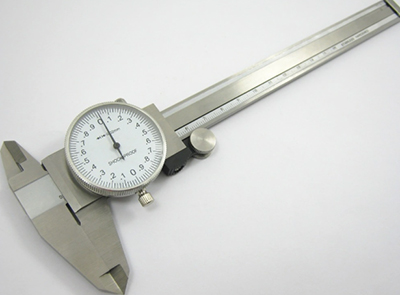
- Calipers for noncritical dimensions
- Surface roughness tester
- Tool presetting system
- Optical comparator or vision measuring system
Critical pocket features may include:
- Overall pocket length and width
- Pocket depth
- Wall thickness
- Bottom flatness
- Internal corner radius
- True position relative to datums
- Perpendicularity of pocket walls
- Surface roughness
For production orders, a first article inspection can confirm the process before full-scale manufacturing. In-process checks can then be performed at defined intervals, such as every 10 or 20 pieces, depending on risk and batch size.
Jixing can support inspection records with dimensional reports and 100% inspection for designated critical characteristics when required by the customer. General quality requirements may be managed under ISO 9001, while material documentation can reference standards such as ASTM B221 for applicable aluminum extruded products. The exact standard should always match the material form and purchase specification.
| Feature | Typical Control Method | Example Requirement |
|---|---|---|
| Pocket width | CMM or calibrated gauge | ±0.01–0.03 mm |
| Pocket depth | Depth micrometer or CMM | ±0.02–0.05 mm |
| Wall thickness | CMM or ultrasonic measurement | According to drawing |
| Surface roughness | Roughness tester | Ra 0.8–3.2 μm |
| Material | Mill certificate and verification | ASTM or EN specification |
| Visual condition | 100% visual inspection | No unacceptable burrs or dents |
These figures are examples, not universal guarantees. The final tolerance depends on part size, alloy, geometry, machine capability, and post-machining treatment.
Common Problems and Practical Corrective Actions
Chatter Marks on Pocket Walls
Possible causes:
- Excessive tool stick-out
- Low workpiece rigidity
- High radial engagement
- Incorrect spindle speed
- Worn tool
- Resonance between tool, holder, and workpiece
Corrective actions:
- Shorten the tool extension
- Reduce radial engagement
- Change spindle speed to move away from resonance
- Use a variable-pitch cutter
- Improve fixture support
- Leave a uniform amount of stock for finishing
Aluminum Sticking to the Cutter
Possible causes:
- Dull or damaged cutting edge
- Insufficient chip evacuation
- Low feed rate
- Excessive heat
- Inadequate lubrication
Corrective actions:
- Replace or clean the cutter
- Use polished aluminum-specific geometry
- Increase chip load within the recommended range
- Improve air blast or coolant flow
- Avoid allowing chips to remain at the pocket bottom
Tapered or Undersized Deep Walls
Possible causes:
- Tool deflection
- Excessive cutting force
- Insufficient finishing allowance
- Long tool reach
- Thermal expansion
Corrective actions:
- Use a more rigid tool and holder
- Reduce depth per pass
- Use a semi-finishing operation
- Finish each wall with a controlled light pass
- Measure the part after thermal stabilization
Poor Pocket-Floor Flatness
Possible causes:
- Tool runout
- Machine-axis misalignment
- Uneven stock after roughing
- Workpiece distortion
- Incorrect finishing direction
Corrective actions:
- Verify spindle and toolholder runout
- Support the workpiece across the fixture
- Add a floor semi-finishing pass
- Use a suitable large-diameter cutter where clearance allows
- Inspect flatness with a CMM or calibrated surface measurement method
Surface Treatment After CNC Milling
Machining marks may become more visible after anodizing, especially when the tool path leaves inconsistent patterns. Surface treatment should therefore be considered during the CNC process, not added as an afterthought.
For anodized aluminum components, we recommend controlling:
- Toolpath direction and overlap
- Burr removal
- Fingerprints and oil contamination
- Surface roughness uniformity
- Edge radii
- Masking areas and datum surfaces
Anodizing can change dimensions, particularly on tight-fitting features. If a pocket receives anodizing, the drawing should identify whether dimensions apply before or after treatment. For a precision fit, Jixing can reserve an allowance or mask selected surfaces, subject to the coating specification.
Chemical conversion coating, hard anodizing, bead blasting, and brushed finishes also create different visual and dimensional effects. The final process should be confirmed before production approval.
A Practical Jixing Checklist Before Production
To make Deep Pocket CNC Milling in Aluminum: How to Maintain Accuracy and Surface Finish more efficient, we recommend confirming the following items before releasing the job:
- Confirm the aluminum alloy and material certification requirement.
- Identify all critical pocket dimensions and datums.
- Check whether internal corner radii are suitable for standard tooling.
- Select the shortest practical end mill and rigid holder.
- Design the fixture to support the cutting area.
- Program adaptive roughing with controlled radial engagement.
- Leave consistent stock for semi-finishing and finishing.
- Plan coolant or air-blast delivery for chip evacuation.
- Define inspection frequency and required reports.
- Confirm whether tolerances apply before or after anodizing.
- Inspect the first article before continuing batch production.
- Record tool life, cutting parameters, and corrective actions.
Using this checklist helps businesses reduce scrap, prevent assembly delays, and maintain consistent quality across repeat orders. It also gives the production team a clear response plan if chatter, burrs, or dimensional drift appears during machining.
Improve Lead Time Without Sacrificing Accuracy
Deep-pocket components often require more machining time than open-profile parts. However, careful process planning can reduce unnecessary operations.
We improve efficiency by:
- Combining compatible features in one setup
- Using standardized fixtures
- Reducing tool changes through proper tool planning
- Applying high-efficiency roughing
- Using probing for workpiece alignment
- Measuring critical features in-process
- Establishing repeatable tool offsets
- Reviewing the design for manufacturability before programming
For export manufacturing projects, clear communication is equally important. A complete drawing, 3D model, tolerance standard, surface-treatment requirement, quantity, and delivery target can prevent repeated clarification. Jixing can provide a response within 24 hours for many machining inquiries when the technical information is complete.
Choose Jixing for Custom Aluminum CNC Machining
Reliable custom aluminum CNC machining depends on more than CNC equipment. It requires engineering review, suitable workholding, controlled tooling, qualified inspection, and documented process discipline.
At Jixing, we treat Deep Pocket CNC Milling in Aluminum: How to Maintain Accuracy and Surface Finish as a complete manufacturing workflow. We evaluate the design, select the correct machining strategy, control cutting conditions, inspect critical features, and coordinate surface treatment requirements before shipment.
When your component includes deep cavities, thin walls, tight tolerances, or a demanding cosmetic finish, send Jixing the 3D model, 2D drawing, material grade, quantity, and finishing specification. We can then recommend a practical process that balances accuracy, surface quality, production efficiency, and total cost.
Conclusion: Maintain Accuracy and Finish with a Controlled Process
The most reliable way to complete Deep Pocket CNC Milling in Aluminum: How to Maintain Accuracy and Surface Finish is to control every stage—from CAD review and fixturing to tool selection, chip evacuation, finishing, and inspection. Short tool stick-out, rigid workholding, adaptive roughing, stable chip load, separate finishing passes, and documented measurement are the essential actions.
We at Jixing use these principles to support repeatable custom aluminum CNC machining for industrial, electronic, automotive, automation, and mechanical applications. By reviewing your pocket geometry and quality requirements before machining begins, we can help reduce chatter, protect surface finish, achieve precision targets such as 0.01 mm, and deliver parts ready for assembly or finishing.


