


Precision hole machining in aluminum CNC parts depends on more than selecting a drill. The machinist must control datum selection, tool runout, chip evacuation, burr formation, temperature, and inspection. For Aluminum CNC Machining Services, the practical method is to locate from the drawing datums, rough-drill below final size, then finish by reaming or circular interpolation. This guide explains how to drill accurate holes in aluminum while controlling hole tolerance, true position, diameter, and surface finish.
Typical failures include holes that are oversized, tapered, bell-mouthed, mislocated, or packed with aluminum chips. These problems become more serious in 6061-T6 and 7075-T6 parts with thin walls, deep holes, tight bolt patterns, or anodized surfaces. Jixing recommends treating the hole as a complete feature: location, diameter, depth, perpendicularity, edge condition, and post-machining inspection must all be specified and verified.
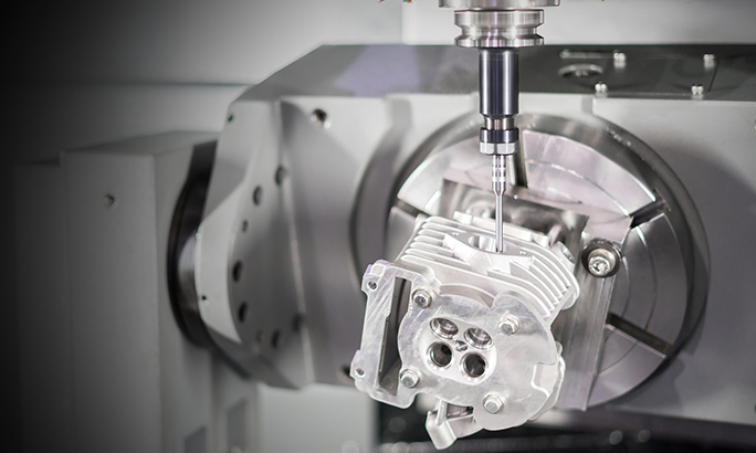
A “precision hole” has several measurable requirements. Diameter alone does not determine whether the feature is acceptable.
- Hole diameter: The actual measured size compared with the drawing limit.
- True position: The location of the hole axis relative to the specified datums, normally controlled with GD&T under ASME Y14.5.
- Perpendicularity: The angular relationship between the hole axis and the referenced surface.
- Depth: The usable cylindrical depth, including any required full-diameter section.
- Surface finish: Commonly specified as Ra, such as Ra 1.6 µm or Ra 3.2 µm, when the drawing requires it.
- Edge condition: Burr height, chamfer size, countersink angle, and damage to the surrounding surface.
For example, a hole specified as Ø10 H7 is not simply a “10 mm hole.” ISO 286 defines the tolerance system, and the exact limits depend on the nominal diameter range. The drawing, not a general machining rule, determines the permitted limits. Likewise, a position tolerance of ⌀0.10 mm at MMC is different from a diameter tolerance of ±0.05 mm.
What Precision Means in Aluminum CNC Machining Services
6061-T6 is widely used because it combines machinability, corrosion resistance, and structural performance. 7075-T6 provides higher strength but can be less forgiving when thin sections deform during clamping. Published material data lists the linear thermal expansion coefficient of many aluminum alloys at approximately 23–24 µm/m·°C near room temperature. A 100 mm aluminum feature changing by 10°C can therefore shift by roughly 0.024 mm. That change is large enough to affect a tight hole tolerance.
Keep the workpiece, cutting tool, coolant, and measuring equipment near the same controlled temperature. ISO 1 establishes 20°C as the reference temperature for dimensional measurement. A shop may machine at a different temperature, but the inspection method should account for thermal differences.
Aluminum Alloy Selection and Thermal Control
Required Preparation for Precision Hole Machining in Aluminum
Before programming, identify the following information from the engineering drawing:
- Hole diameter and tolerance class.
- Hole depth and whether the bottom is blind-hole or through-hole geometry.
- Location dimensions or true-position callouts.
- Primary, secondary, and tertiary datums.
- Required countersink, counterbore, chamfer, or thread.
- Surface-finish requirement.
- Material and temper, such as 6061-T6 or 7075-T6.
- Post-processing requirements, including anodizing, plating, or chemical conversion coating.
Do not use general tolerances as a substitute for a missing critical tolerance. If the drawing is unclear, obtain engineering clarification before cutting material. A hole may be dimensionally correct but rejected because its true position or perpendicularity is outside the drawing requirement.
Drawing, Datum, and Tolerance Preparation
- Three-axis or five-axis CNC machining center with a rigid spindle.
- Precision vise, soft jaws, fixture plate, or vacuum fixture selected for the part geometry.
- Calibrated edge finder, probe, or optical alignment system.
- Carbide or polished high-speed-steel aluminum drill.
- Solid-carbide end mill for circular interpolation where appropriate.
- Machine reamer or adjustable reamer for tight cylindrical tolerances.
- Spot drill or non-walking drill-point tool.
- Coolant system capable of delivering fluid to the cutting zone.
- Calibrated pin gauges, bore gauge, micrometer, height gauge, or CMM.
- Deburring tool, countersink, nylon abrasive brush, or controlled edge-finishing tool.
Confirm tool diameter, flute geometry, coating, gauge length, coolant compatibility, and maximum recommended speed from the tool manufacturer. Aluminum-specific polished flutes and high helix geometry generally provide better chip evacuation than a tool intended for steel, but the tool maker’s data takes priority over generic feeds and speeds.
Tools and Equipment for How to Drill Accurate Holes in Aluminum
Measure runout at the cutting edge or near the tool tip with a test indicator. The acceptable value depends on the hole tolerance, tool diameter, holder type, and machine condition. For a tight hole, runout should be substantially smaller than the permitted diameter variation; otherwise, the tool may cut unevenly and produce an oversized or lobed hole.
Check spindle taper cleanliness, collet condition, tool-holder balance, axis backlash, and coolant concentration. A clean holder and correctly tightened collet are basic requirements, not optional improvements.
Tool Runout and Machine Condition
Step-by-Step Aluminum CNC Machining Services Process
Tools: Soft jaws, fixture plate, torque wrench, parallels, dial indicator, and workholding stop.
Action: Clean the fixture and workpiece. Support the part close to the hole pattern and avoid clamping across thin unsupported walls. Use the drawing datums to establish the setup. For a thin plate, distribute clamping force over a broad area rather than tightening one small contact point.
Parameters: Use the fixture manufacturer’s torque specification. Do not estimate clamping torque for a delicate part. Keep the locating surfaces free from chips; one trapped chip can shift the workpiece or tilt it.
Check: Sweep the primary datum with an indicator. Confirm that the part is seated and that the indicator variation is within the setup allowance defined by the drawing or process plan.
Failure fix: If the part rocks, the indicator varies unexpectedly, or the hole pattern is consistently displaced, stop machining. Clean the locating surfaces, inspect for burrs, and redesign the support rather than compensating with an arbitrary coordinate offset.
1. Stabilize and Fixture the Aluminum Part
Tools: Touch probe, edge finder, indicator, or calibrated optical system.
Action: Locate the part from the same datums used in the drawing. Record the work offset and verify the coordinate direction. For a hole pattern, use a probing routine that checks more than one reference surface when the drawing requires angular or positional control.
Parameters: Use the probing manufacturer’s calibrated stylus diameter and probing speed. Apply the correct probe radius compensation. Do not mix an edge-finder offset with a touch-probe offset without verification.
Check: Probe a known feature or reference edge twice. The repeated result should remain within the machine’s documented probing repeatability and the job’s setup allowance.
Failure fix: If repeated probing results differ, inspect for chips, burrs, probe deflection, loose fixturing, or incorrect stylus calibration. Re-probing will not solve a physically unstable setup.
2. Probe or Pick Up the Datums
Tools: Aluminum-specific spot drill or small carbide end mill.
Action: Create a controlled entry surface before deep drilling. A spot drill should form a shallow, concentric starting feature rather than a wide, deep countersink. For a thin wall or angled surface, circular interpolation may provide better control than a conventional spot drill.
Parameters: Use the tool maker’s recommended aluminum cutting speed and feed. Keep the spot depth only as deep as required to guide the following tool. Excessive spot depth can increase work-hardening risk, create a large burr, or reduce the remaining wall thickness.
Check: Inspect the spot location against the programmed coordinates and confirm that the entry is centered and free of built-up aluminum.
Failure fix: If the spot is off-center, check work offset, tool runout, tool geometry, and the fixture. Do not continue with the final drill because the entry error will usually be transferred to the hole.
3. Spot Drill or Interpolate the Entry
Tools: Polished-flute aluminum drill, through-tool coolant if available, and chip-removal equipment.
Action: Drill below the final diameter when the drawing requires reaming or precision interpolation. Use a rigid, short-gauge-length tool whenever possible. For through-holes, program a controlled breakthrough and provide clearance below the part. For blind holes, verify the actual flute length and programmed point depth.
Parameters: Select spindle speed and feed from the drill manufacturer’s aluminum data. The basic relationship is:
Use peck drilling only when the hole depth, chip evacuation, or machine coolant delivery requires it. Excessive pecking can increase cycle time and leave marks in the bore. A continuous feed is often preferable for short, well-lubricated holes when chips evacuate freely.
Check: Inspect the first hole for diameter, breakthrough burr, chip packing, taper, and surface damage. Use a pin gauge or bore gauge appropriate to the tolerance. Never force a gauge through a hole; forcing can damage both the gauge and the part.
Failure fix: For an oversized hole, inspect runout, tool wear, holder condition, and drill geometry. For chip packing, improve coolant direction, reduce chip load only within tool-maker limits, use a suitable peck cycle, or select a drill with better flute geometry. For a tapered hole, check rigidity, tool deflection, and breakthrough support.
4. Rough-Drill the Hole
Tools: Machine reamer, boring tool, or solid-carbide end mill suited to helical interpolation.
Action: Choose the finishing process according to the feature. Reaming is efficient for repeated holes with a standard diameter and adequate alignment. Circular interpolation is useful when the CNC machine must correct location, when different diameters are required, or when the hole is close to a thin wall. Boring provides another option for high control over diameter and alignment.
Parameters: Leave the stock recommended by the reamer manufacturer. Removing too little stock can cause rubbing; removing too much can overload the tool and produce poor geometry. Reaming feed is normally controlled separately from drilling feed, so use the manufacturer’s data rather than copying the drilling program.
Check: Measure the first finished hole at more than one depth when the tolerance is tight. Compare the entry, middle, and bottom readings to identify taper or bell-mouth geometry. Check surface finish if specified.
Failure fix: If the reamed hole is oversized, inspect reamer runout, stock allowance, coolant, and tool wear. If the hole is rough, look for chip recutting, insufficient lubrication, or a damaged reamer. If circular interpolation leaves faceting, reduce tool deflection, use a suitable step-over, and verify machine interpolation accuracy.
5. Finish the Hole by Reaming or Circular Interpolation
Tools: Chamfer mill, countersink, counterbore, thread mill, or tap.
Action: Perform edge finishing after the cylindrical hole has been verified, unless the process plan specifically requires another sequence. Use thread milling for critical threads when positional control and chip management are important. If tapping, confirm the tap drill size, thread form, lubricant, and required thread depth.
Parameters: Program the chamfer diameter or depth from the drawing. A chamfer that is only 0.1 mm larger than intended can affect a sealing face, fastener seating, or minimum edge distance.
Check: Measure countersink diameter, included angle, thread depth, and remaining edge margin. Use a calibrated thread plug gauge for internal threads where specified.
Failure fix: If the countersink is uneven, inspect tool runout and hole alignment. If the thread is torn, check tap drill size, lubrication, chip evacuation, and synchronization. Do not use a larger tap drill as an uncontrolled correction without engineering approval.
6. Add Chamfers, Countersinks, Threads, or Counterbores
Tools: Controlled deburring blade, nylon brush, low-pressure air, aqueous washer, and lint-free cloth.
Action: Remove the entry and exit burr with a controlled, repeatable method. Avoid aggressive hand sanding around a precision hole because it can enlarge the mouth and create a lead-in chamfer larger than the drawing allows.
Parameters: Define the permitted burr height or edge break in the drawing or inspection plan. Keep compressed air away from personnel and use eye protection. Remove chips from blind holes before inspection.
Check: Use visual inspection, a fingertip-safe edge check, a magnifier, or a burr-height comparator. Verify that cleaning has not removed material from the functional diameter.
Failure fix: If the hole mouth is oversized, replace uncontrolled manual deburring with a guided chamfer tool or machine-controlled edge break. If chips remain, use flushing, ultrasonic cleaning, or a validated wash process.
7. Deburr and Clean Without Changing the Geometry
Tools: Pin gauges, calibrated bore gauge, air gauge, CMM, vision system, surface-finish tester, and height gauge.
Action: Inspect diameter, location, depth, perpendicularity where required, surface finish, and burr condition. For a hole pattern, inspect the pattern relative to the drawing datums rather than measuring each hole only from a nearby edge.
Parameters: Use calibrated equipment with a suitable resolution and uncertainty for the tolerance. ISO/IEC 17025 is the relevant competence standard for calibration and testing laboratories. Record equipment identification, calibration status, temperature, operator, and measurement result.
Check: First-article inspection should confirm the setup before production continues. For critical parts, use a CMM report or another method capable of measuring true position. Apply the drawing’s MMC and bonus-tolerance rules correctly; do not replace GD&T calculations with a simple coordinate measurement.
Failure fix: If the diameter passes but true position fails, correct the datum setup, work offset, fixture location, or machine geometry. If the position passes but diameter fails, correct the tool path, tool wear compensation, reamer condition, or cutting parameters. Segregate nonconforming parts and document the disposition.
8. Inspect the Finished Hole and Hole Pattern
- — ISO system of limits and fits.
- — Dimensioning and tolerancing principles, including true position and datum references.
- — Standard reference temperature of 20°C for geometrical product specifications and verification.
- — Competence requirements for testing and calibration laboratories.
- — Aluminum alloy and temper information.
Tool cutting data should come from the specific drill, reamer, end mill, machine, and coolant manufacturer. Published values are starting points, not guarantees. Tool diameter, flute count, holder runout, machine rigidity, alloy temper, hole depth, and coolant delivery all affect the correct setting.
Verified Technical References for Aluminum Hole Machining
Common Aluminum CNC Hole-Machining Errors and Solutions
Common causes include excessive tool runout, a worn drill, poor holder grip, built-up edge, or insufficient rigidity. Measure runout, clean the taper, replace the tool, and verify that the tool is designed for aluminum. If the hole remains oversized, finish it with a controlled reaming or boring operation rather than increasing the programmed offset blindly.
Oversized or Lobed Holes
This usually indicates tool deflection, angular setup error, or a hole that is not perpendicular to the locating surface. Check the fixture, spindle alignment, tool gauge length, and machine geometry. A CMM or bore-measuring system can distinguish location error from angular error.
Hole Location Is Correct at the Top but Wrong at the Bottom
Built-up edge changes the effective tool diameter and can damage the bore. Use a sharp polished-flute aluminum tool, adequate lubrication, correct chip evacuation, and manufacturer-approved cutting conditions. Stop the operation if aluminum is visibly adhering to the cutting edge.
Aluminum Welds to the Cutting Tool
Exit burrs increase when the drill breaks through unsupported material or when the tool is dull. Add a sacrificial backing plate where the design permits, reduce breakthrough stress using an appropriate feed strategy, and use a controlled deburring operation. Do not remove a large burr by aggressive hand grinding around a tolerance hole.
Large Exit Burrs
Anodizing adds an oxide layer to the surface. The dimensional effect depends on the coating type, thickness, process, alloy, and whether the coating grows inward, outward, or both. When a finished hole must meet a tight tolerance, define the requirement after coating and obtain the anodizer’s process capability data. Do not assume that a pre-anodize hole will remain within the same limit.
Hole Size Changes After Anodizing
Excessive clamping force, heat, and unbalanced support can distort an aluminum component. Use distributed support, reduce unnecessary cutting heat, inspect with the specified fixturing condition, and document whether the tolerance applies in a free state or restrained state.
Thin Parts Deform During Machining or Inspection
A common engineering use case described by the ASME Y14.5 system is a bolt-hole pattern controlled by a position tolerance relative to datums. In that situation, a hole can have an acceptable diameter and still fail because its axis is outside the allowed positional zone. The practical lesson is directly applicable to CNC production: inspect the hole pattern from the drawing datums, report actual coordinates, and evaluate the positional tolerance according to the feature-control frame.
This is a standards-based use case rather than an invented customer testimonial. Private production records should not be presented as verified personal stories unless the customer, drawing, inspection report, and permission to publish are available. Jixing can support a documented case report when those records are authorized for release.
Documented Case Use: Applying GD&T Instead of Measuring Only Diameter
For repeat production, create a control plan that links each hole requirement to a process and inspection method. A practical plan may include:
- Verify material certificate and alloy temper before machining.
- Confirm fixture datum surfaces and setup repeatability.
- Measure tool runout during setup for tight-tolerance holes.
- Use a first-piece inspection before releasing the batch.
- Monitor tool life by hole count, measured diameter, or cutting load.
- Inspect hole diameter and position at the frequency defined by the risk assessment.
- Record temperature and calibration status for critical measurements.
- Inspect post-anodizing dimensions when the finished coating is part of the requirement.
Do not promise a universal tolerance from a material name alone. The achievable result depends on the machine, fixture, geometry, tool, inspection method, and drawing requirement. When requesting aluminum CNC machining services, provide the alloy, quantity, CAD file, drawing, hole tolerances, position callouts, surface-finish requirements, coating condition, and inspection standard.
Production Recommendations from Jixing
Reliable holes come from a controlled sequence: interpret the datums, stabilize the workpiece, verify tool runout, create a centered entry, drill with controlled chip evacuation, finish by reaming, boring, or interpolation, deburr without enlarging the mouth, and inspect both diameter and true position. Thermal expansion, fixture distortion, built-up edge, and coating growth must be included in the process plan.
The most useful final check is not “does the drill fit?” It is whether the finished feature satisfies every drawing requirement at the correct inspection temperature and datum reference. For production parts, Jixing’s engineering team can review the drawing and recommend an appropriate process route for precision hole machining in aluminum CNC parts, aluminum CNC machining services, and how to drill accurate holes in aluminum while controlling hole tolerance, burr-free drilling, aluminum alloy behavior, peck drilling, GD&T true position, and reaming.


